Table of Contents >> Show >> Hide
- Introduction: The Lightning Machine With a Brain
- What Makes a Solid-State Tesla Coil Different?
- The Golden Rule: Design Around Resonance
- SSTC or DRSSTC: Choosing the Right Architecture
- The Main Parts of a Great Solid-State Tesla Coil
- Safety Design Is Not Optional
- Grounding, EMI, and the Art of Not Annoying the Neighborhood
- Mechanical Build Quality: The Invisible Performance Upgrade
- Testing and Tuning Without Drama
- Common Mistakes That Ruin Otherwise Good Coils
- Builder Experience: Lessons From the Bench
- Conclusion: Build for Sparks, Tune for Reliability
Safety note: A solid-state Tesla coil is not a toy, even when it fits on a workbench and looks cute enough to deserve a nickname. This guide is educational and design-focused, not a complete construction manual. Solid-state Tesla coils involve high voltage, high current, stored energy, radio-frequency fields, hot semiconductors, possible fire hazards, and electromagnetic interference. Build only if you understand electronics safety, use proper enclosures, fuse protection, emergency shutoff methods, isolation practices, discharge procedures, and adult supervision where appropriate. Never touch arcs, never operate near people with electronic medical implants, and never treat “small coil” as a synonym for “safe coil.”
Introduction: The Lightning Machine With a Brain
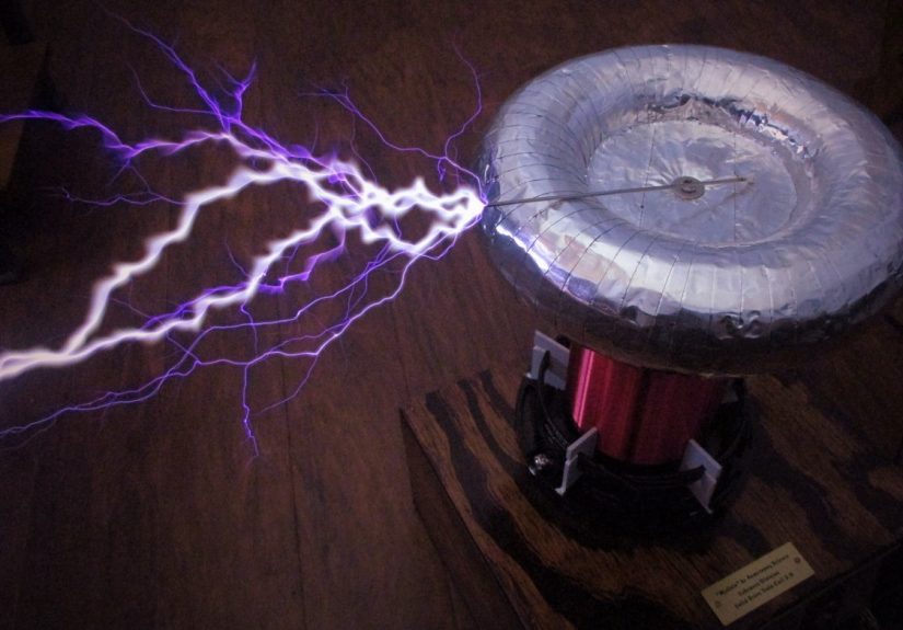
A solid-state Tesla coil is what happens when classic high-voltage showmanship meets modern power electronics. Instead of a noisy spark gap doing the switching, an SSTC uses semiconductor devices such as MOSFETs or IGBTs to drive a resonant coil at high frequency. The result is cleaner control, better repeatability, musical modulation possibilities, and fewer of the chaotic “why did that capacitor just become confetti?” moments that haunt old-school high-voltage benches.
The perfect solid-state Tesla coil is not simply the one with the longest spark. A truly excellent build is stable, tunable, safe to operate, electrically clean, mechanically solid, and forgiving enough that one small mistake does not instantly turn the bridge into a tiny fireworks display. It has a well-wound secondary, a sensible top load, a driver that respects timing, a power stage that stays cool, feedback that behaves, and a builder who knows when to stop increasing the input power. That last part is difficult. The knob is right there. It whispers.
This builder’s guide walks through the major design choices behind a reliable SSTC or DRSSTC: resonance, coil geometry, switching devices, gate drive, interrupters, grounding, protection, testing, tuning, and the practical lessons that separate a polished build from a glowing pile of lessons learned.
What Makes a Solid-State Tesla Coil Different?
A traditional spark-gap Tesla coil uses a primary capacitor, a primary coil, and a spark gap to create bursts of radio-frequency energy. A solid-state Tesla coil replaces the spark gap with electronic switching. That change may sound simple, but it transforms the personality of the machine. Instead of waiting for a spark gap to fire, the builder can command the power stage with timing circuits, feedback systems, pulse-width control, MIDI interrupters, optical links, and fault protection.
In a basic SSTC, the secondary coil is the main resonant element. The driver senses or estimates the secondary’s resonant frequency and pushes energy into it at the right time. In a dual-resonant solid-state Tesla coil, or DRSSTC, the primary circuit also has a resonant capacitor, creating a tuned primary tank that can move very high peak currents. That is why DRSSTCs can produce dramatic arcs from relatively compact hardware. It is also why they demand more respect. A DRSSTC can look calm on the outside while the primary tank is hosting a private wrestling match between hundreds of amps and very expensive silicon.
The Golden Rule: Design Around Resonance
The soul of a Tesla coil is resonance. The secondary coil, its self-capacitance, and the top load form a resonant circuit. When the driver excites that circuit at or near its natural frequency, voltage rises efficiently. When it drives far away from resonance, performance drops, components heat, and the builder starts blaming perfectly innocent parts.
A practical design begins by choosing the physical size of the secondary. Small tabletop coils may use a narrow secondary form with many turns of fine magnet wire. Larger coils use wider forms, taller windings, and more robust mechanical support. The top load, usually a toroid or smooth metal sphere, adds capacitance to the top of the secondary. That lowers the resonant frequency and helps control where breakout occurs. A smooth toroid often lets voltage build before a streamer begins, while a small breakout point gives the discharge a preferred place to start. Without a breakout point, a coil may choose its own exit path, and it is rarely polite enough to ask first.
For builders, the practical lesson is simple: do not treat the secondary, top load, and driver as separate projects. They are one system. Change the top load, and the resonant frequency changes. Move the primary, and coupling changes. Add nearby metal, and tuning can shift. Even the room can become part of the experiment if the coil is large enough.
SSTC or DRSSTC: Choosing the Right Architecture
Basic SSTC
A basic SSTC is usually the better starting point for learning solid-state Tesla coil design. It can be built at lower power, uses fewer energy-storage components than a DRSSTC, and teaches the builder about gate drive, feedback, grounding, layout, and secondary behavior without immediately throwing extreme primary tank currents into the mix. Basic SSTCs can produce impressive corona and modest streamers, and many can be audio modulated.
DRSSTC
A DRSSTC is the performance machine. By tuning the primary tank and secondary resonator, it can transfer energy more aggressively. It is commonly operated in short bursts controlled by an interrupter, keeping average power manageable while allowing high peak current during each burst. This architecture is the reason musical Tesla coils can produce sharp, loud, dramatic sparks that seem to dance in rhythm.
The tradeoff is complexity. DRSSTCs need current limiting, reliable overcurrent detection, careful primary capacitor selection, strong bus capacitors, robust IGBTs, proper snubbers or transient suppression, clean gate drive, and disciplined testing. In other words, a DRSSTC is not the first date. It is meeting the family, discussing finances, and assembling furniture together.
The Main Parts of a Great Solid-State Tesla Coil
1. The Secondary Coil
The secondary should be wound neatly, evenly, and patiently. Magnet wire spacing matters because random overlaps can create weak spots in insulation. A smooth winding also reduces unpredictable corona points. Many builders seal the secondary with varnish, polyurethane, or epoxy-compatible coatings to protect the winding and improve durability. The winding form should be dry, clean, nonconductive, and mechanically stable.
A good secondary is not just pretty; it is predictable. Before designing the power stage, estimate or measure the secondary’s resonant frequency with its intended top load installed. A coil that looks perfect but resonates far outside the comfortable range of the driver may become a beautiful shelf decoration.
2. The Top Load
The top load shapes the electric field and adds capacitance. A toroid is popular because its rounded surface discourages random breakout and supports longer, more controlled streamers. Size matters. Too small, and the coil may break out early with short, fuzzy corona. Too large, and the driver may struggle to push the resonator efficiently, or breakout may become reluctant. The sweet spot depends on secondary size, power level, and desired behavior.
A breakout point is often added to control where arcs begin. This reduces the chance of streamers striking downward into sensitive electronics. It is not a magic shield, but it is much better than letting high voltage improvise.
3. The Primary System
In a basic SSTC, the primary is often a few turns of heavy wire around the base of the secondary. In a DRSSTC, the primary becomes part of a resonant tank with a capacitor bank. The primary must handle high current and strong magnetic fields. Use mechanically secure conductors and keep high-current loops compact. Loose wiring in a Tesla coil is not “flexible design.” It is an audition for smoke.
Coupling between primary and secondary must be chosen carefully. Too little coupling wastes performance. Too much coupling can cause racing sparks along the secondary, unstable tuning, and flashovers. The primary should be positioned so the system transfers energy effectively without over-stressing the secondary insulation.
4. The Power Switches: MOSFETs and IGBTs
MOSFETs are common in lower-power and higher-frequency SSTCs because they can switch quickly. IGBTs are common in DRSSTCs because they tolerate high current better in many high-power applications, although they generally switch more slowly than MOSFETs. The right device depends on bus voltage, switching frequency, current, pulse duration, thermal design, and protection strategy.
Never choose switches by headline ratings alone. A device that claims heroic current capacity on a datasheet may only do so under conditions your coil will never see. Look at pulsed current, switching losses, safe operating area, gate charge, package thermal resistance, voltage margin, and how the device behaves during fault conditions. Silicon is honest, but only after it fails.
5. The Gate Driver
The gate driver is the translator between delicate logic and the power stage. It must charge and discharge the MOSFET or IGBT gates quickly and cleanly. Weak gate drive causes slow switching, excess heat, and cross-conduction risk. Poor layout adds ringing, false triggering, and noise sensitivity. Isolation is often used to separate control electronics from the violent electrical neighborhood of the bridge.
Good gate-drive design includes proper gate resistors, short gate loops, adequate supply decoupling, dead time where needed, and clear separation between logic ground and power ground. A gate driver should not be treated as a decorative chip placed somewhere near the transistors. It is one of the most important parts of the system.
6. Feedback and Interruption
Many SSTCs use feedback from the secondary base current, an antenna, or another sensing method to lock the drive to the resonant frequency. Feedback helps the system follow changes caused by streamer loading, top load changes, and environmental effects. However, feedback must be conditioned carefully so noise does not produce false triggering.
An interrupter turns the RF drive on and off in pulses. This controls duty cycle, limits average power, and enables musical operation. In a musical coil, the interrupter converts note information into timed bursts. The arc does not behave like a hi-fi speaker, of course. It is more like a plasma kazoo with lightning privileges. Still, with good timing and sensible pulse limits, the results can be surprisingly musical.
Safety Design Is Not Optional
The best Tesla coil builders design safety into the machine before the first spark. A safe layout includes a main disconnect, fuses or breakers appropriate to the system, bleeder resistors on capacitors, a visible power indicator, an emergency stop, insulated enclosures, strain relief, protective earth bonding, and a clear operating perimeter. Stored energy must be discharged before servicing. Capacitors can remain dangerous after power is removed, and assuming they are empty is a classic way to have a very bad afternoon.
RF burns are another hazard. Tesla coil arcs may not feel like ordinary low-frequency electric shocks, but they can still burn tissue and create dangerous current paths. Keep hands, tools, jewelry, phones, watches, and random “let me try something” friends away from the discharge area. People with pacemakers or other electronic medical implants should not be near an operating coil because electromagnetic interference can affect medical devices.
Ventilation matters too. Corona and arcs can create ozone and nitrogen oxides. Short demonstrations in a ventilated shop are one thing; long indoor runs in a small room are another. If the room smells like a thunderstorm that went to chemistry class, stop and ventilate.
Grounding, EMI, and the Art of Not Annoying the Neighborhood
A solid-state Tesla coil is an RF machine. It can radiate noise, upset nearby electronics, and create strange behavior in cables that were minding their own business. Keep control wiring short, shielded where appropriate, and physically separated from high-current switching paths. Fiber-optic links are popular in higher-performance systems because they provide electrical isolation and reduce noise pickup.
Grounding should be planned, not guessed. Protective earth, RF ground, logic ground, and power return are not always the same thing. Mixing them carelessly can inject noise into the driver or create hazardous touch conditions. For small coils, a carefully designed grounded enclosure and proper mains wiring may be sufficient. For larger coils, dedicated RF grounding and shielding may be needed. Avoid using household wiring as a casual RF return path. Your router, smart TV, and neighbor’s radio will not applaud.
Mechanical Build Quality: The Invisible Performance Upgrade
Many Tesla coil failures are blamed on electronics when the real problem is mechanical. Loose terminals heat up. Vibration works screws free. Sharp metal edges invite corona. Dust creates leakage paths. Acrylic panels crack if stressed. Heat sinks underperform if mounted poorly. A perfect schematic cannot rescue a messy build.
Use proper standoffs, insulated supports, clean solder joints, crimped or bolted high-current connections, and physical barriers between low-voltage controls and high-voltage sections. Label connectors. Add strain relief. Provide airflow. Mount the bridge where it can cool. Place status LEDs where they can be seen without reaching over the danger zone. In short, build the coil as if future-you will be tired, distracted, and holding a multimeter. Future-you will appreciate the kindness.
Testing and Tuning Without Drama
The first power-up should be boring. That is the goal. Begin with visual inspection, continuity checks, isolation checks, correct polarity checks, gate-drive waveform checks, and low-voltage testing before applying serious bus voltage. Confirm that the interrupter works. Confirm that overcurrent protection trips. Confirm that fans spin in the correct direction. Confirm that the emergency stop actually removes power. Do not discover these things during a streamer strike.
Use a current-limited supply or staged input power during early testing. Watch waveforms with appropriate probes and safe measurement practices. A standard oscilloscope ground clip in the wrong place can create fireworks faster than you can say, “I thought that was isolated.” If you do not have the right measurement equipment, borrow it, buy it, or reduce the ambition of the build.
Tuning is a process of small changes and careful observation. Adjust primary tap position, coupling, breakout point, interrupter pulse width, and power level gradually. Keep notes. Record what changed, what improved, and what got hot. The builder who writes things down looks like a genius later, mostly because everyone else forgot what happened ten minutes ago.
Common Mistakes That Ruin Otherwise Good Coils
One common mistake is overdriving the coil before it is tuned. More input power does not fix poor resonance; it simply makes the problem louder. Another mistake is underestimating gate-drive layout. Long gate leads and weak decoupling can turn a bridge into a radio receiver for its own noise. A third mistake is ignoring thermal design. Semiconductor devices may survive short tests but fail during longer runs if heat cannot escape.
Builders also get into trouble by placing control electronics too close to the secondary, skipping bleeder resistors, using capacitors not rated for pulse service, trusting breadboards for high-speed power circuits, or running without a hard safety perimeter. Breadboards are wonderful for blinking LEDs. They are not wonderful for angry RF power stages.
Builder Experience: Lessons From the Bench
The first lesson a solid-state Tesla coil teaches is humility. On paper, everything looks tidy: resonance frequency calculated, bridge selected, interrupter ready, secondary wound, top load polished. Then the real world arrives wearing muddy boots. The resonant frequency shifts when the toroid is mounted. The breakout point changes arc behavior. A wire that seemed short enough becomes an antenna. A heat sink that looked enormous gets uncomfortably warm. The coil reminds you that electricity reads the whole layout, not just the schematic.
One of the best practical habits is to build in layers. Do not assemble the entire coil and then apply full power as if launching a rocket. Test the logic section first. Then test the gate-drive signals into dummy loads. Then verify the interrupter at low duty cycle. Then test the bridge at low bus voltage. Then bring the resonator into the picture. This staged approach may feel slow, but it is much faster than replacing blown transistors, cracked resistors, and your confidence.
Another experience-based rule: neatness is performance. The cleanest coils usually run better because the builder has controlled parasitic inductance, minimized loop area, separated noisy and sensitive sections, and made inspection easy. A messy build can work, but it gives every fault a hiding place. When a coil fails, you need to see what happened. Was it a loose primary connection? A flashover track? A scorched gate resistor? A capacitor lead that vibrated loose? Good layout turns troubleshooting from detective fiction into engineering.
Cooling deserves more respect than beginners give it. Short bursts can hide thermal problems. A bridge may survive a few dazzling sparks and still be heading toward failure after repeated operation. Fans, heat sinks, thermal compound, proper mounting pressure, and airflow paths are not glamorous, but they are cheaper than silicon. After testing, use a safe shutdown procedure, wait, discharge stored energy, and then inspect for heat discoloration, smells, loose hardware, and dust paths. Your nose is not a calibrated instrument, but if something smells roasted, believe it.
The final bench lesson is restraint. The perfect solid-state Tesla coil is not the one pushed hardest. It is the one that performs consistently, shuts down safely, survives repeated runs, and teaches everyone watching something about resonance, power electronics, and respect for electricity. Long arcs are fun. Reliable long arcs are better. Reliable long arcs from a coil that does not terrify the builder are best of all.
Conclusion: Build for Sparks, Tune for Reliability
A perfect solid-state Tesla coil is a balanced machine. The secondary must resonate cleanly, the top load must shape breakout, the primary must couple energy without abusing the winding, the bridge must switch within its limits, the gate driver must stay clean, and the safety system must be treated as part of the design rather than an accessory. The goal is not merely to create sparks; it is to create controlled, repeatable, educational sparks without turning the workbench into a cautionary tale.
Start modestly, test patiently, document everything, and respect the machine. A solid-state Tesla coil rewards careful builders with one of the most spectacular demonstrations in electronics: invisible resonance becoming visible lightning. That is hard to beat. Even coffee looks boring afterward.