
Table of Contents >> Show >> Hide
- From Simple Touch Buttons to DIY Multitouch
- What “Arduino Does Multitouch” Is Actually About
- Why Multitouch on Arduino Matters
- How Arduino Does Multitouch: Conceptual Walkthrough
- Practical Project Ideas Using Arduino Multitouch
- Limitations and Trade-Offs
- Lessons from the Multi-Touch Kit Research
- Real-World Experiences with Arduino Multitouch (Maker’s Perspective)
- Conclusion
Once upon a time, your Arduino was thrilled to toggle an LED or read a humble pushbutton.
Then smartphones arrived, and suddenly every surface was a silky, glassy multitouch wonder.
If you’ve ever looked at your Uno and thought, “Why can’t you do that?”, the
“Arduino Does Multitouch” project from Hackaday and the research behind the
Multi-Touch Kit are basically your dream come true.
Thanks to clever capacitive sensing tricks and an open-source toolkit, you can turn simple
materialscopper tape, foil, cardboard, acrylic, even paperinto custom multitouch pads.
With a regular Arduino as the sensing engine and a PC handling the heavy math, you get
high-resolution multitouch input without buying an expensive commercial touchscreen controller.
In this guide, we’ll unpack how Arduino does multitouch, what the Multi-Touch Kit is, what
you need to build your own pad, and how you can actually put it to work in real projects.
Think of it as a friendly, slightly nerdy tour through the world of DIY capacitive multitouch.
From Simple Touch Buttons to DIY Multitouch
Before we get into multitouch magic, it helps to understand how Arduino usually handles touch.
The classic approach uses capacitive sensing: the Arduino charges and discharges
a sensor pad and measures how long it takes. Your finger adds a tiny bit of capacitance, so
the timing changes, and the code says, “Aha, someone touched me.”
Libraries like the well-known CapacitiveSensor library for Arduino make this
easy, letting you turn bits of aluminum tape or copper pads into single touch buttons without
special ICs. On the more advanced side, breakout boards like the
MPR121 12-key capacitive touch controller or TTP229-based keypads give you
multiple touch inputs over I2C with built-in filtering and thresholds.
Traditionally, however, these setups are single touch per pad. Great for “play a note
when this pad is touched,” but not enough if you want full multitouch gestures like pinch,
zoom, or two-finger sliders. That’s where the research behind the
Multi-Touch Kit and the Hackaday “Arduino Does Multitouch” write-up comes in:
they show how to extract multitouch data from what looks like simple capacitive hardware,
powered by nothing more exotic than an Arduino and clever signal processing on a PC.
What “Arduino Does Multitouch” Is Actually About
The Hackaday project centers on a research paper called
“Multi-Touch Kit: A Do-It-Yourself Technique for Capacitive Multi-Touch Sensing Using a
Commodity Microcontroller”. In plain English: it’s a toolkit that lets makers and designers
rapidly create custom multitouch surfaces using inexpensive materials and a standard Arduino-class
microcontroller.
Instead of buying a dedicated, closed-box multitouch controller, you:
- Build a grid of electrodes (rows and columns) using copper tape, PCB traces, or printed conductive ink.
- Use the Arduino to scan the grid, measuring capacitive changes across intersections.
- Send those measurements via serial to a PC application built with Processing and OpenCV.
- Let the PC perform the heavy computation to locate and track multiple fingers simultaneously.
The result is a flexible, customizable multitouch pad whose size, shape, and layout are up to you.
You can build a long, thin slider, a circular control wheel, or a laptop-sized trackpad, simply by
changing how you lay out your electrodes.
Hardware Ingredients
At a high level, the hardware behind “Arduino Does Multitouch” looks like this:
- Arduino board: Tested with boards like the Uno, Mega, and LilyPad. Any board with enough pins and stable timing can work.
- Electrode grid: Strips of copper tape, aluminum tape on a substrate, or a custom PCB forming rows and columns.
- Multiplexing or selection circuitry (optional): Analog multiplexers or similar components to scan many electrodes with fewer pins.
- Ground/reference plane: Sometimes a ground layer or shield is used to improve signal quality and reduce noise.
Unlike hobby I2C touch shields that do everything internally, here the Arduino
is the sensing engine. That’s powerful because you control the sampling strategy,
thresholds, and timingbut it also means you have to be more thoughtful about your design.
The Software Stack
On the software side, multitouch on Arduino is a team effort:
- Arduino firmware handles low-level capacitive measurements and streams values over serial.
- Processing-based PC app receives the data, transforms it into a 2D image of touch intensities, and uses OpenCV to detect and track multiple fingertips.
- Multi-Touch Kit library (Arduino + Processing) is provided as open source so you can tweak and extend it.
This division of labor keeps the Arduino code relatively lightweight while leveraging the PC’s CPU for
math-heavy image processing and gesture recognition. For many DIY use casesart installations, prototypes,
lab experimentshaving a PC in the loop is perfectly acceptable.
Why Multitouch on Arduino Matters
So why go through all this trouble when cheap phone screens exist? A few big reasons:
- Custom shapes and sizes: Commercial touchscreens are rectangles. DIY capacitive grids can be long strips, rings, curves, or cut-to-shape panels.
- Material freedom: You can embed electrodes into wood, acrylic, textiles, foam board, or cardboard, and make interactive furniture, walls, or wearables.
- Cost and accessibility: Copper tape and an Arduino are inexpensive and widely available. No need for specialized controller chips.
- Educational value: For classrooms and labs, building the sensor from scratch is a great way to teach electronics, HCI, and signal processing.
The Multi-Touch Kit and Hackaday’s coverage both highlight the same goal: make multitouch a
fabrication technique, not just a mysterious black box you buy and bolt on.
How Arduino Does Multitouch: Conceptual Walkthrough
You don’t need to reproduce the exact research setup to get started. Here’s a high-level way to think
about building your own Arduino multitouch pad.
1. Design the Electrode Layout
First, choose the size and shape of your pad. For example:
- A 10×10 grid of squares for a trackpad-like surface.
- A 4×12 strip to create a piano-style keyboard.
- A ring of wedges for a radial menu or jog dial.
Each intersection or cell represents an area where one or more fingers can be detected. The resolution of your grid
dictates how precisely you can localize touchesmore electrodes mean finer detail but more wiring and more data
for the Arduino to scan.
2. Build the Sensor with Everyday Materials
For quick experiments, makers often use:
- Aluminum or copper tape: Adheres to cardboard, acrylic, or foam board and forms conductive traces.
- Thin plastic or paper overlays: For smoothing the surface and protecting the metal from direct contact.
- Flexible substrates: PET sheets or fabric for bendable multitouch surfaces.
The main layout idea is to have “transmit” lines running one way and “receive” lines running perpendicular. The
capacitance between them changes when a finger comes close, because your body couples to the field and slightly
alters the electric characteristics at that intersection.
3. Scan the Grid with the Arduino
In simplified terms, the Arduino:
- Drives one transmit line with a signal (for example, a pulse train or modulated waveform).
- Measures the response on each receive line, which depends on the mutual capacitance between the lines.
- Repeats this for each transmit line, building a 2D array of readings.
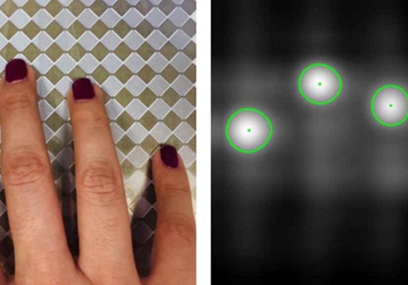
That 2D array is essentially a “touch image” brighter areas mean stronger capacitance changes, which usually
indicate fingertips. Because your hand covers more than one cell, interpolation and filtering on the PC side
can locate touch centers and track multiple contacts.
4. Process the Data on the PC
On the computer, a Processing sketch or similar app:
- Reads the serial data stream from the Arduino.
- Normalizes and filters it to reduce noise and drift.
- Maps readings into a grayscale “heatmap” image.
- Uses computer vision algorithms to find blobs (fingertips) and track their movement across frames.
From there, you can map gestures to events: two fingers moving apart triggers zoom, three-finger swipes switch modes,
and so on. You can also bridge this into other software, such as MIDI controllers, game input, or custom interactive
installations.
Practical Project Ideas Using Arduino Multitouch
Once your Arduino does multitouch, it’s hard not to see possible uses everywhere. A few starter ideas:
- DIY MIDI controller: Turn a multitouch strip into a pressure-sensitive keyboard, with velocity based on touch intensity or movement speed.
-
Interactive coffee table: Embed electrodes under a glass tabletop and trigger ambient lighting or soundscapes
when people trace patterns on the surface. -
Educational lab panel: Build a modular multitouch “whiteboard” where students can directly manipulate graphs,
sliders, and regions with two-hand gestures. -
Tangible UI experiments: Combine multitouch sensing with 3D-printed shapes or cardboard cutouts so that touching
different regions of a model triggers different digital responses.
Because you control the electrode pattern, there’s no need to shoehorn your interaction into a rectangular screen.
The touch surface becomes another material in your toolbox, just like wood, acrylic, or fabric.
Limitations and Trade-Offs
Of course, there are some caveats:
- PC dependency: In the classic Multi-Touch Kit setup, the PC does the heavy processing. For fully embedded products, this may be a deal-breaker.
- Noise and stability: DIY layouts can be noisy. Power supply quality, grounding, and shielding matter more than you might expect.
- Scan rate vs. resolution: More electrodes mean more data to scan. At some point, you must trade spatial resolution for update speed.
- Mechanical robustness: Tape-based prototypes may wear out, peel, or suffer from inconsistent contact over time.
Still, for prototyping, art, research, and learning, a multitouch Arduino rig is incredibly powerful. And the more
you refine your layout, shielding, and filtering, the closer you’ll get to that smooth, smartphone-like feel.
Lessons from the Multi-Touch Kit Research
The research behind “Arduino Does Multitouch” is packed with insights that you can apply even if you don’t follow
their implementation exactly:
- Start from simple materials: The system is designed to work with common conductive foils and fabrication tools, not exotic lab gear.
- Use frequency-based sensing: Scanning at multiple frequencies and analyzing responses helps distinguish meaningful touches from noise.
- Think like an image-processing problem: Once your readings form a 2D map, you can borrow techniques from computer vision, not just raw thresholding.
- Design for novices: The toolkit is aimed at makers and interaction designers, not just embedded-systems experts. Your own projects should be approachable, too.
Perhaps the biggest takeaway is philosophical: multitouch doesn’t have to be locked inside commercial touch controllers.
With a commodity microcontroller and the right algorithms, you can pull that intelligence into your own designs and
shape it to match your ideas.
Real-World Experiences with Arduino Multitouch (Maker’s Perspective)
It’s one thing to read about “Arduino does multitouch” and another to live with copper tape stuck to everything you own.
Here’s what the experience typically looks like when you dive in.
The first version of a multitouch pad is often gloriously ugly: a piece of foam board with wobbly strips of copper tape,
half-peeled masking labels, and wires sprouting from one side like techno-spaghetti. You spend an afternoon carefully
laying out a grid, label everything, and proudly connect it to the Arduino. You open the Processing sketch, tap the pad…
and the readings explode with random noise whenever someone walks across the room or a fluorescent light flickers.
That’s your first big lesson: electromagnetic noise is real. Suddenly you care about twisted wires,
shielded USB cables, and solid ground references. Maybe you add a thin grounded layer beneath the pad, or move the
Arduino closer to the electrodes to shorten leads. Each tweak makes the touch blobs on your screen more stable and
less jittery. It’s oddly satisfying to see those noisy blobs “snap” into clean, round touch spots after a small wiring fix.
The next learning curve is calibration. Dry winter air? Capacitance readings drift. Someone rests their palm
on the edge of the pad? Baseline shifts. You start building routines to auto-calibrate on startup or periodically
recenter the baseline. You experiment with thresholds so that light brushes register as touches without letting
random noise trigger ghost fingers. Eventually, you develop a feel for your sensor’s personalityhow much hysteresis it
needs, how fast it can respond before it becomes unstable.
Then comes the fun part: mapping gestures to behavior. One early multitouch experiment might be a simple
two-octave piano. You tap multiple “keys” at once and watch your MIDI monitor light up with chords instead of single notes.
A three-finger swipe could change instruments; a long press might toggle sustain. Once you’ve seen two-finger control feel
natural on a pad you built yourself out of cardboard and tape, it’s hard not to smile.
In workshop or classroom settings, Arduino-based multitouch is a fantastic conversation starter. Students who might be
intimidated by IC datasheets can immediately understand a sheet of copper tape electrodes. They can literally see their
touches visualized on the screen like glowing blobs, and that tight feedback loop makes debugging feel more like a game
than a chore. When someone accidentally tears a strip of tape and the sensor still works after a quick patch, it opens a
door to talk about fault-tolerant layouts and even cuttable multi-touch surfaces.
Over time, you also develop a sense for what Arduino multitouch is best at. It might not replace a high-end laptop
trackpad for pixel-perfect GUI control, but it shines in installations, experiments, and custom interfaces where the shape,
size, and context really matter. A curved control panel on a synth, a touch-enabled poster at a museum, a desk that responds
when you draw paths with your fingertipsthese are the kinds of projects where “Arduino does multitouch” stops being a
headline and becomes a design philosophy.
And yes, you will still occasionally find bits of copper tape stuck to your socks months later. Consider it a badge of honor.
Conclusion
The idea behind “Arduino Does Multitouch | Hackaday” is simple but powerful: you don’t have to treat multitouch
as a mysterious feature that only phones and tablets can have. With the Multi-Touch Kit approach, some conductive material,
and an Arduino, you can design surfaces that understand multiple fingers, complex gestures, and custom layouts tailored to
your projectnot the other way around.
Whether you’re a hobbyist looking to build a quirky interactive table, an educator exploring hands-on HCI lessons, or a
designer prototyping new tangible interfaces, Arduino-powered multitouch gives you the flexibility of custom hardware with
the familiarity of the Arduino ecosystem. It’s a great reminder that with the right tools and a bit of curiosity, even a
tiny microcontroller can learn some very big-screen tricks.