
Table of Contents >> Show >> Hide
- Safety First (Yes, Really)
- Know Your Baldor Motor Before You Wire It
- How to Wire a Baldor 3 Phase Motor: 13 Steps
- Step 1: Confirm the power system and motor match
- Step 2: Plan the control method (starter vs. VFD)
- Step 3: Lock out and tag out (LOTO) the circuit
- Step 4: Verify absence of voltage (do the “live-dead-live” routine)
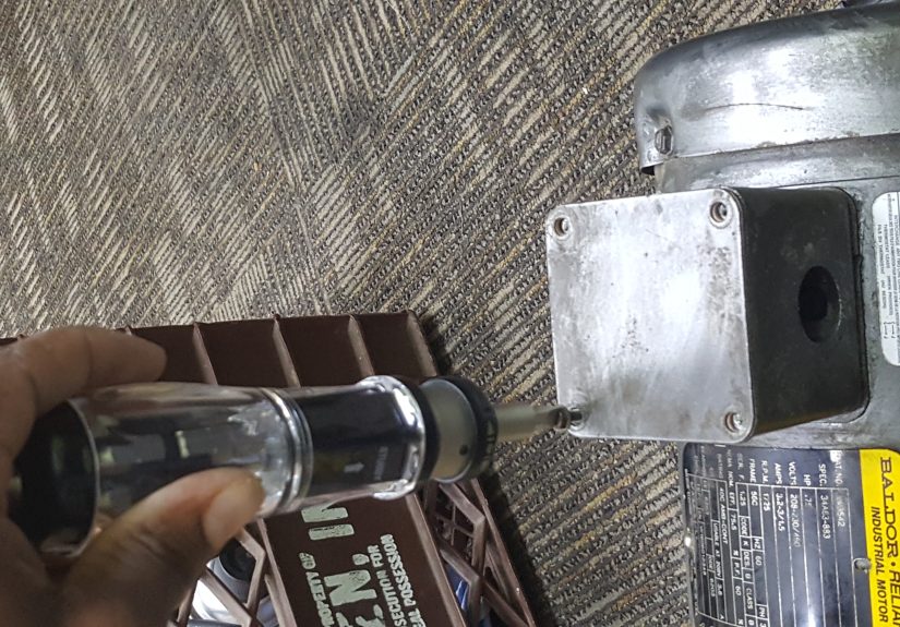
- Step 5: Open the motor conduit box and inspect
- Step 6: Identify and label the leads
- Step 7: Choose the correct voltage connection (common 9-lead example)
- Step 8: Make the motor lead splices clean and secure
- Step 9: Connect the line conductors (L1, L2, L3) to the motor leads
- Step 10: Ground the motor properly
- Step 11: Recheck everything (the “three passes” rule)
- Step 12: Jog test for rotation (then fix it the easy way)
- Step 13: Run test under load and compare current to nameplate
- Common Mistakes (and How to Avoid the Sad Trombone Sound)
- Quick Troubleshooting Checklist
- Conclusion
- Extra: Real-World Experiences and Lessons from Wiring Baldor 3-Phase Motors (500+ Words)
Wiring a Baldor 3-phase motor is one of those jobs where everything is calm and logical… right up until it isn’t. The good news: most Baldor (ABB/Baldor-Reliance) motors are designed to be straightforward to connect, with a connection diagram on (or inside) the motor that tells you exactly what to do. The bad news: electricity is not forgiving, and “I thought that was the ground” is not a fun sentence to say out loud.
This guide walks you through 13 practical steps to wire a typical Baldor 3-phase induction motorespecially common dual-voltage motors (230/460V) with T-leads (T1–T9). We’ll keep it clear, safe, and just funny enough to keep the “magic smoke” inside the windingswhere it belongs.
Safety First (Yes, Really)
Warning: Motor wiring can expose you to lethal voltage and arc-flash hazards. If you are not trained and qualified to work inside electrical enclosures, stop here and hire a licensed electrician. Always follow your facility’s lockout/tagout (LOTO) procedures, applicable codes, and the exact motor connection diagram supplied by the manufacturer.
Tools and materials you’ll typically need
- Proper PPE for the hazard category in your facility (face shield, gloves, etc.)
- Lockout/tagout devices (lock, tag, hasp as needed)
- Multimeter (properly rated) and/or voltage tester
- Insulated hand tools (screwdrivers, nut driver, cutters/strippers)
- Crimp tool and terminals/lugs (as required by your terminal box/starter)
- Wire nuts or insulated connectors rated for the conductor and enclosure (industrial-rated, not bargain-bin)
- Cable glands/strain relief and conduit fittings
- Motor starter/contactor + overload relay (or a VFD) sized for the motor
- Optional but smart: clamp meter, insulation resistance tester (“megger”) for stored/old motors
Know Your Baldor Motor Before You Wire It
1) Read the nameplate like it’s the plot twist
The motor nameplate (or documentation) tells you the essentials: voltage (often 208–230/460V), full-load amps (FLA), frequency (60 Hz in most U.S. installations), RPM, and sometimes service factor and enclosure type. Wiring a dual-voltage motor for the wrong supply is one of the fastest ways to turn a perfectly good motor into a very expensive paperweight.
2) Find the motor connection diagram
On many Baldor motors, the diagram is on the nameplate, inside the conduit box cover, or included in the paperwork. That diagram is the authority. This article provides common wiring patterns, but your motor’s diagram wins every argument, every time.
3) Understand the leads (T1–T9 and friends)
Many industrial 3-phase motors use numbered leads (often labeled T1, T2, T3…). Dual-voltage motors frequently have 6 leads or 9 leads. A 9-lead motor is extremely common in U.S. shops and plants because it supports flexible low/high voltage connections.
How to Wire a Baldor 3 Phase Motor: 13 Steps
-
Step 1: Confirm the power system and motor match
Verify your supply: Is it 208V, 230V, 460/480V, or something else? Confirm the motor is rated for that voltage and that you’re wiring it for the correct configuration. Dual-voltage motors are not “auto-sensing.” They are “do what the diagram says.”
-
Step 2: Plan the control method (starter vs. VFD)
Decide whether the motor will be run across-the-line with a motor starter/contactor + overload relay or controlled by a VFD. This matters because VFD installations often require additional grounding/shielding practices and may change how you route and terminate cables. If a VFD manufacturer provides a wiring diagram, follow it.
-
Step 3: Lock out and tag out (LOTO) the circuit
Shut down the equipment, open the disconnect/breaker feeding the motor circuit, and apply lockout/tagout. Do not rely on a start/stop button, selector switch, or interlock as your “disconnect.” Those are control devices, not energy isolation.
-
Step 4: Verify absence of voltage (do the “live-dead-live” routine)
Use properly rated test equipment to confirm the circuit is de-energized. A best practice is the “live-dead-live” approach: verify your meter on a known live source, test the target circuit for absence of voltage phase-to-phase and phase-to-ground, then verify the meter again on a known live source. If you skip this, you’re basically trusting your life to a tool you haven’t proven is working. That’s a bold strategy.
-
Step 5: Open the motor conduit box and inspect
Remove the motor terminal box cover. Look for moisture, damaged insulation, loose hardware, burned smells, or any previous “creative” wiring. If the motor has been stored or exposed to damp conditions, consider insulation resistance testing before energizing.
-
Step 6: Identify and label the leads
You should see motor leads labeled T1–T9 (or sometimes numeric tags). If tags are missing or illegible, stop and trace/identify properlyguessing is how motors die. Arrange the leads so you can clearly see what will be tied together and what will connect to line power.
-
Step 7: Choose the correct voltage connection (common 9-lead example)
For a common 9-lead, dual-voltage, WYE motor (typical in U.S. industrial settings), the wiring often looks like this:
Typical LOW voltage (230V) connection (9-lead WYE style)
- Connect (tie together): T4 + T5 + T6
- L1 to: T1 + T7
- L2 to: T2 + T8
- L3 to: T3 + T9
Typical HIGH voltage (460V) connection (9-lead WYE style)
- L1 to: T1
- L2 to: T2
- L3 to: T3
- Connect (tie pairs): T4 + T7, T5 + T8, T6 + T9
Important: This is a common pattern, but your Baldor motor’s diagram might differ (some motors are delta-connected internally, some have 12 leads, some have special starting methods). Use the manufacturer diagram to confirm.
-
Step 8: Make the motor lead splices clean and secure
When you tie leads together (like T4+T5+T6), use connectors rated for the conductor type, temperature, and enclosure. Make tight, solid connectionsloose splices create heat, and heat creates regret. Dress wires so the cover will close without pinching insulation.
-
Step 9: Connect the line conductors (L1, L2, L3) to the motor leads
Route the three phase conductors from your starter/VFD/disconnect into the motor box using proper conduit fittings and strain relief. Land L1/L2/L3 exactly as required by the chosen motor lead configuration (and the diagram). Torque terminals to specification if provided.
-
Step 10: Ground the motor properly
Connect the equipment grounding conductor to the motor’s ground screw/grounding point inside the terminal box. Ensure you have a solid metallic bond to the motor frame. Grounding is not a “nice to have.” It’s a core safety requirement, and it also helps reduce electrical noise issuesespecially if you’re using a VFD.
-
Step 11: Recheck everything (the “three passes” rule)
Before you close the box, do a deliberate review:
- Do the lead ties match the correct voltage diagram?
- Are all splices tight and insulated?
- Is the ground connected?
- Are there any stray wire strands or copper “hair” near terminals?
- Is the conduit fitting secure and providing strain relief?
Pro tip: read the diagram once, wire it, then read it again as if you’re trying to catch someone else’s mistake. That someone else is also you.
-
Step 12: Jog test for rotation (then fix it the easy way)
Reinstall covers, clear the area, remove tools, and re-energize following your site procedures. Do a brief “jog” (quick start/stop) to check rotation. If rotation is wrong, power down, lock out again, verify absence of voltage, and swap any two line conductors (e.g., swap L1 and L2). That reverses a 3-phase motor direction without changing your internal motor lead connections.
-
Step 13: Run test under load and compare current to nameplate
Let the motor run long enough to stabilize. Measure current on each phase (clamp meter) and compare to the nameplate FLA. Current should be reasonably balanced across phases. If the motor is pulling high current, running rough, or tripping overloads, shut down and investigate: incorrect lead connections, wrong voltage, mechanical load issues, phase loss, or control settings (especially on a VFD) can all cause problems.
Common Mistakes (and How to Avoid the Sad Trombone Sound)
Wiring for 230V on a 460V supply
This can damage the motor quickly. Always confirm the supply voltage and wire the motor accordingly.
Skipping overload protection
Branch-circuit protection (breakers/fuses) is not the same as motor overload protection. A properly selected overload relay helps protect the motor from overheating under overload conditions. Use a motor starter/overload relay or VFD protection features as required by your design and code.
Assuming “off” means safe
A switch in the OFF position is not the same as verified de-energized. Lock out, tag out, and test before touching conductors.
Quick Troubleshooting Checklist
- Motor hums but won’t start: possible single-phasing, wrong connections, mechanical binding, or low voltage.
- Overload trips quickly: wrong voltage configuration, load too heavy, miswired starter/overload settings, phase imbalance.
- Runs backward: swap any two line leads (after LOTO and verification).
- Excessive heat/noise: incorrect wiring, poor ventilation, bearing issues, misalignment, or VFD settings (carrier frequency, accel time).
Conclusion
Wiring a Baldor 3-phase motor isn’t about memorizing one magic diagramit’s about following a repeatable process: verify the supply, use the motor’s connection diagram, make solid terminations, ground correctly, and test safely. Do that, and your motor will spin happily for years. Skip steps, and you may get a short, dramatic lesson in why electricians drink coffee like it’s a job requirement.
Extra: Real-World Experiences and Lessons from Wiring Baldor 3-Phase Motors (500+ Words)
If you spend enough time around industrial motors, you start collecting the same “greatest hits” storiesbecause the same small mistakes show up in different disguises. Here are a few real-world patterns technicians commonly run into when wiring a Baldor 3-phase motor (or any similar dual-voltage workhorse), plus what those moments teach.
The “It Worked Yesterday” Mystery
One of the most common service calls starts with: “We didn’t change anything.” Then you open the motor box and find a conductor that’s been slowly loosening itself for months. Vibration is relentless, and a slightly loose termination can act fine until it heats up, oxidizes, and becomes a tiny space heater. Lesson: torque matters. If your facility uses torque specs and documented checks, it’s not bureaucracyit’s motor life insurance.
The “Dual Voltage” Confidence Trap
Dual-voltage motors create a false sense of security. People see “230/460” and think the motor will figure it out. It won’t. The motor will do exactly what you told it to do with the leadsand if that doesn’t match the supply, it will either underperform (wired high, fed low) or fail spectacularly (wired low, fed high). Lesson: the nameplate is your friend, and the connection diagram is your boss.
The Rotation Mix-Up That Costs an Afternoon
On pumps, fans, and compressors, rotation matters. A motor spinning the wrong direction can reduce flow, damage equipment, or trigger alarms. The good news is that reversing a 3-phase motor is usually simple: swap any two line leads. The bad news is when someone swaps internal motor lead groupings insteadturning a five-minute fix into an hour of “Wait, which ones were tied again?” Lesson: keep voltage configuration (the internal ties) separate from rotation correction (swap two line conductors).
The “Ground Is Optional” Myth
Occasionally, you’ll see a motor wired with beautiful, color-coded conductors… and a missing ground. Sometimes it’s accidental, sometimes it’s “temporary.” Temporary grounds have a habit of becoming permanent until the worst possible moment. Beyond shock protection, a solid ground can reduce electrical noise and help VFD installations behave better. Lesson: grounding isn’t an accessoryfinish the job.
The Starter/Overload Settings Nobody Touched
A motor can be wired perfectly and still trip because the overload relay is set wrong, sized wrong, or not matched to the motor’s FLA and application. In the field, it’s common to see an overload dial left at the previous motor’s setting. Then the new motor “mysteriously” trips under normal load. Lesson: after wiring, confirm protection and settings. Wiring is half the story; protection is the other half.
The Best Habit: Make a Final “Calm Check” Non-Negotiable
The most experienced techs tend to do one thing consistently: they slow down at the end. They re-read the diagram, confirm every tie, confirm the ground, confirm strain relief, then close up neatly. This final calm check prevents the classic failurespinched insulation, loose splices, wrong voltage configurationthat cause call-backs and downtime. Lesson: the last two minutes often decide whether the next two days are peaceful.
In short: wiring a Baldor 3-phase motor is rarely hard, but it is always exact. Respect the diagram, respect the safety steps, and you’ll get the best kind of result: a motor that runs quietly while you take the credit.