
Table of Contents >> Show >> Hide
- What Is a Short Circuit Tracer?
- Why “For a Buck” Matters
- The Problem With Continuity Mode
- How a Budget Short Circuit Tracer Works
- Why Four-Wire Measurement Is the Secret Sauce
- Common Causes of PCB Short Circuits
- Safe Setup for Low-Voltage Short Finding
- Step-by-Step: Using a Budget Short Circuit Tracer
- Short Circuit Tracer vs. Thermal Camera
- Short Circuit Tracer vs. Bench Power Supply Only
- Where This Method Works Best
- Practical Example: Shorted Buck Converter Output
- Mistakes to Avoid
- Experience Notes: What Working With Cheap Short Tracers Teaches You
- Conclusion
A short circuit on a circuit board is one of those problems that looks simple until it laughs at you from underneath a tiny capacitor. Your multimeter says, “Beep! Yes, there is a short.” Wonderful. Thank you, tiny plastic oracle. But where is it? That is the real mystery. A short circuit tracer for a buck is the low-cost answer: a simple, clever way to turn basic test gear into a practical PCB short-finding tool without buying a professional micro-ohm meter, thermal camera, or lab-grade fault locator.
The idea is not magic. It is measurement. Instead of only asking whether two points are connected, a short circuit tracer helps you follow the resistance path across a board. When current flows through copper traces, vias, solder joints, and the fault itself, tiny voltage differences appear. If you can measure those differences carefully, you can “walk” toward the lowest-resistance point and find the short. It is a little like following breadcrumbs, except the breadcrumbs are millivolts and the forest is full of 0402 capacitors waiting to ruin your afternoon.
This guide explains how a budget short circuit tracer works, why a normal continuity test is not enough, how four-wire resistance measurement improves accuracy, and how hobbyists and repair technicians can use low-voltage, current-limited methods to locate shorts safely on low-voltage electronics.
What Is a Short Circuit Tracer?
A short circuit tracer is a troubleshooting tool used to locate the physical point where two electrical paths are unintentionally connected. On a PCB, that may mean a solder bridge between pins, a failed ceramic capacitor shorted to ground, a damaged IC, a metal shaving, a burned trace, or a manufacturing defect hiding under a component.
A standard multimeter continuity mode can confirm that a short exists. It sends a small test current through the circuit and beeps when resistance is low enough. That is useful, but it does not tell you whether the short is under the USB-C port, beside the buck converter, inside the power management IC, or under that suspicious capacitor that looks innocent because components have excellent poker faces.
A tracer goes further. It helps locate the short by comparing small resistance or voltage-drop changes along the path. The closer your probes move toward the short, the lower the measured resistance usually becomes, or the voltage pattern changes in a predictable way. With patience, you can narrow a large board down to a specific area and, often, a single component.
Why “For a Buck” Matters
The phrase “for a buck” captures the spirit of the project: cheap, practical, and surprisingly useful. Professional short finders, micro-ohm meters, and thermal cameras can be excellent, but not everyone wants to spend serious money to diagnose a dead laptop board, a failed Arduino shield, or a homemade PCB that refuses to behave.
A low-cost short circuit tracer usually depends on tools many electronics hobbyists already own: a digital multimeter, a current-limited bench power supply, test leads, clips, and sometimes a small add-on circuit or probe arrangement. The goal is not to replace professional equipment. The goal is to make the invisible visible enough that you can stop guessing.
The Problem With Continuity Mode
Continuity mode is the first tool many people use because it is fast. Touch the probes together, hear a beep, and feel briefly powerful. On a simple wire or fuse, that works beautifully. On a crowded PCB, continuity mode can become misleading.
Modern circuit boards often have large ground planes, multiple capacitors connected in parallel, low-resistance power rails, inductors, IC pins, and protection diodes. A normal meter may beep across a rail even when the “short” is not a hard fault, especially on low-voltage power rails designed to feed processors, GPUs, or memory. Some rails naturally measure very low resistance because they power many devices at once.
That is why context matters. A beep between 5V and ground on a simple sensor board may be a clear problem. A low reading on a CPU core rail may be normal. The tracer does not replace judgment; it gives you better information so your judgment has something stronger than vibes and burnt-flux smell.
How a Budget Short Circuit Tracer Works
The basic method is simple: apply a safe, limited current through the shorted path, then measure tiny voltage differences along the board. Ohm’s law does the heavy lifting. Current flowing through a small resistance creates a small voltage drop. If you use a sensitive voltmeter, you can detect that drop and follow it toward the fault.
For example, imagine a 5V rail is shorted to ground. You do not blast it with 5V at unlimited current, because that is how boards become decorative smoke machines. Instead, you use a current-limited supply set to a low voltage, often below the normal operating voltage of the rail, and a conservative current limit. Then you probe along the rail. The closer you get to the short, the voltage gradient changes. The shorted component may also warm slightly, which can confirm the location if done carefully.
Another method uses low-resistance measurement. If your meter can resolve small changes, you probe different points on the same shorted net. The point with the lowest resistance to the opposite rail is often closest to the fault. Ordinary two-wire resistance measurements include probe resistance and lead resistance, so the readings may jump around. That is where four-wire measurement becomes important.
Why Four-Wire Measurement Is the Secret Sauce
Four-wire measurement, also called Kelvin measurement, separates the current path from the voltage-sensing path. Two wires force current through the device or board path being tested, while two separate sense wires measure voltage directly at the test points. This reduces the error caused by test lead resistance, clip resistance, and imperfect contact pressure.
In normal two-wire resistance mode, your meter measures everything in the loop: the board, the probes, the wires, oxidation, pressure from your hand, and possibly your impatience. When trying to distinguish between 0.08 ohms and 0.05 ohms, that extra resistance can bury the useful signal. Four-wire measurement makes tiny resistance differences easier to see.
A DIY “short circuit tracer for a buck” often borrows this principle. Even if it is not a laboratory-grade Kelvin setup, the design tries to isolate the measurement from the worst lead-resistance errors. That is the reason such a cheap idea can work surprisingly well.
Common Causes of PCB Short Circuits
Solder Bridges
Solder bridges are among the most common causes of shorts, especially on fine-pitch ICs, connectors, and hand-soldered boards. A tiny blob can connect adjacent pins and create a direct path where none should exist. Under magnification, the bridge may look obvious. Without magnification, it may look like “why does this board hate me?”
Failed Ceramic Capacitors
Multilayer ceramic capacitors can fail short, especially after mechanical stress, overvoltage, manufacturing defects, or board flex. Because decoupling capacitors are often placed between power and ground, a single failed capacitor can make an entire rail appear shorted.
Damaged ICs
Power management ICs, buck converters, USB interface chips, and microcontrollers can fail internally. When silicon fails short, the outside may look perfect. A tracer can help you discover that the fault is not the obvious connector but the chip sitting three centimeters away pretending to be royalty.
Metal Debris and Flux Contamination
Loose wire strands, solder balls, metal shavings, and conductive contamination can create intermittent or permanent shorts. Cleaning the board and inspecting under light and magnification should always be part of the process.
Design or Assembly Errors
A PCB footprint error, reversed component, wrong part value, misplaced zero-ohm link, or soldered jumper can cause a short. When working on prototypes, never assume the board layout is innocent. Schematics and layouts can be wrong with a confidence that is almost inspiring.
Safe Setup for Low-Voltage Short Finding
Before using any short tracing method, disconnect the board from its normal power source. Remove batteries, unplug adapters, and avoid live circuits. These techniques are meant for low-voltage electronics, not mains wiring, high-voltage power supplies, or anything connected directly to AC line power.
Use a current-limited bench supply whenever injecting current. Start low. A common repair approach is to use a low voltage and a current limit appropriate for the board size and rail. Small logic boards may need only tens or hundreds of milliamps. Larger power rails may tolerate more, but guessing is risky. The goal is to create enough signal to locate the fault, not to cook the board like a snack.
Touch components carefully. Some parts may heat quickly. If anything becomes hot fast, disconnect power. Heat can help identify the short, but excessive heat can damage pads, traces, IC packages, batteries, and nearby plastic parts.
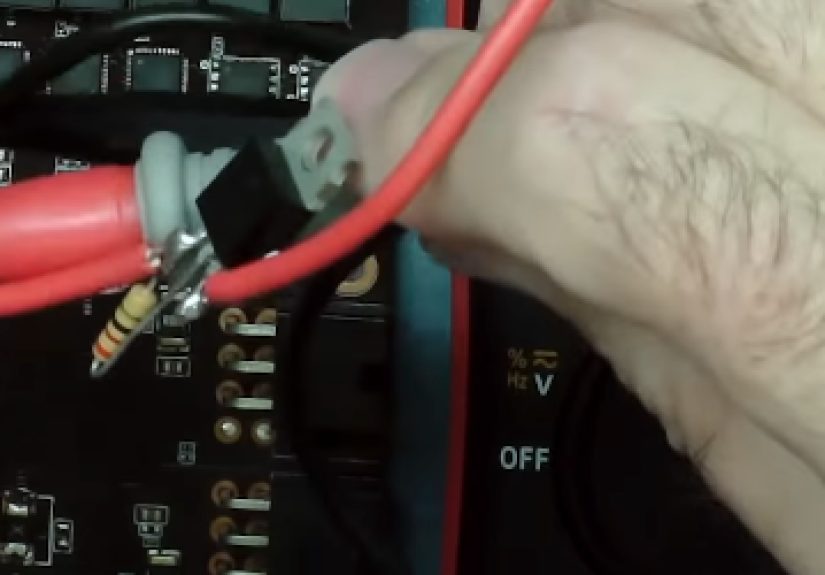
Step-by-Step: Using a Budget Short Circuit Tracer
1. Confirm the Short
Use a multimeter in resistance or continuity mode to verify the suspected short. Compare the reading to a known-good board if available. If the rail is naturally low resistance, do not jump to conclusions.
2. Inspect Visually
Look for obvious solder bridges, damaged parts, cracked capacitors, burned areas, loose screws, and corrosion. A five-minute visual inspection can save an hour of advanced detective work.
3. Identify the Shorted Net
Determine which power rail or signal line is shorted. Use schematics, board markings, regulator outputs, inductor locations, and capacitor placement to map the affected area.
4. Inject Limited Current
Connect a current-limited supply across the shorted rail and ground. Use low voltage and a conservative current limit. Watch the current display. If the supply immediately hits current limit, you have confirmed a low-resistance path.
5. Probe for Voltage Drop
Use a sensitive voltage range on your DMM. Measure along the rail at different points. Changes in millivolts can indicate where current is flowing. Move gradually toward the area with the strongest clue.
6. Compare Resistance Paths
If using a milliohm-style method, probe different points and watch for the lowest resistance reading. The shortest electrical path to the fault often produces the lowest reading.
7. Confirm With Heat or Freeze
A thermal camera, isopropyl alcohol evaporation, or freeze spray can help reveal the component dissipating power. Use these methods gently. The fastest-warming part is not always the failed part, but it is usually worth investigating.
8. Remove the Suspect Component
Once you identify a likely failed capacitor or IC, remove it carefully and test the rail again. If the short disappears, you found the culprit. If not, keep tracing. Electronics troubleshooting rewards patience and mildly stubborn optimism.
Short Circuit Tracer vs. Thermal Camera
A thermal camera is one of the fastest ways to find some shorts. Inject a limited current, watch for a hot spot, and the failed part may reveal itself in seconds. However, thermal cameras cost more than a one-dollar tracer, and not every short creates a clear thermal signature. Large copper planes can spread heat, tiny components may heat too quickly, and some shorts occur in places the camera cannot see.
A budget tracer is slower but cheaper. It is also useful when the current must be kept very low, when the board is too crowded for thermal clarity, or when you want to understand the current path rather than only find the warmest part.
Short Circuit Tracer vs. Bench Power Supply Only
A current-limited bench supply is extremely useful, but by itself it may only tell you that current is flowing. The tracer technique adds direction. It turns current injection into a map. You are not just powering the short; you are measuring the trail that leads to it.
That said, the bench supply must be used carefully. Constant-current behavior does not make a board invincible. A tiny IC can still be damaged by heat if too much current flows for too long. Always begin conservatively, increase only when necessary, and stop when the clues are clear.
Where This Method Works Best
A low-cost short circuit tracer works well on many low-voltage boards: development boards, small power supplies, LED controllers, laptop daughterboards, phone accessory boards, audio gadgets, sensor boards, and homemade PCBs. It is especially helpful when the short is on a power rail with several capacitors or components connected in parallel.
It is less effective when a board has huge internal planes, many parallel low-resistance paths, buried faults, or a rail that naturally measures very low. In those cases, the voltage gradient may be difficult to interpret. The method still helps, but you may need schematics, boardview software, thermal imaging, or component isolation.
Practical Example: Shorted Buck Converter Output
Suppose a buck converter output rail reads nearly zero ohms to ground. The board will not power on, and the regulator gets no chance to start. A normal continuity test only confirms the obvious: the output is shorted.
You disconnect normal power and inject a low, current-limited voltage into the shorted output rail. Then you probe around the output inductor, output capacitors, load IC, and nearby vias. One capacitor shows the lowest resistance path and warms slightly when current is applied. You remove it, test again, and the short is gone. The buck converter now starts normally after replacing the capacitor.
This is the kind of repair where a budget tracer shines. Without it, you might remove parts randomly. With it, you follow evidence.
Mistakes to Avoid
Do not inject normal operating voltage into an unknown short. Do not use high current just because the board is “already dead.” Dead boards can become more dead, and they rarely apologize. Do not use this method on mains-powered circuits unless you are trained and equipped for high-voltage safety. Do not hold probes loosely and trust unstable readings. Probe pressure matters when measuring tiny resistance changes.
Also, do not assume the first warm part is automatically bad. Sometimes current flows through a good component on its way to the bad one. Use multiple clues: resistance direction, voltage drop, thermal behavior, schematic location, and visual inspection.
Experience Notes: What Working With Cheap Short Tracers Teaches You
The first lesson is humility. A one-dollar short circuit tracer can outperform guessing, but it will not turn anyone into an instant repair wizard. The tool gives clues, and the user must interpret them. On simple boards, the process feels almost magical. You probe around, the readings guide you across the copper, and suddenly the bad capacitor practically waves at you. On dense boards, the readings can be subtle, and every via seems to whisper, “Maybe it is me.”
One useful habit is to write down readings instead of trusting memory. When tracing a shorted rail, measure at the regulator output, both sides of the inductor, several decoupling capacitors, connector pins, and any large IC power pins. Even a simple table of millivolt readings can reveal a pattern. The lowest resistance or strongest voltage-drop clue often forms a trail. Without notes, it is easy to circle the board three times and end up accusing the same innocent capacitor repeatedly.
Another experience-based lesson is that cleaning matters. Flux residue, dust, and old repair debris can make visual inspection harder. Before doing delicate tracing, clean the area with appropriate electronics cleaner or high-purity isopropyl alcohol, then inspect under magnification. Many “mysterious” shorts are not mysterious at all. They are tiny solder balls hiding between pins like criminals in chrome jackets.
Probe quality also matters more than beginners expect. Dull probes slip. Oxidized tips create inconsistent contact. Long floppy leads add noise and frustration. Fine needle probes, Kelvin-style clips, or sharpened probe tips can make low-resistance tracing much more repeatable. When dealing with millivolt-level clues, stable contact is the difference between useful data and electronic astrology.
Patience is the final tool. Current injection may need several careful attempts. Thermal clues may take a few seconds to appear. Some shorted capacitors heat gently; others do not heat much at all because copper planes spread the energy. In those cases, the tracer method still helps by narrowing the search area. Once the suspect zone is small, removing one capacitor at a time becomes a controlled diagnostic step rather than a desperate harvesting operation.
The best experience with a cheap short circuit tracer is the moment you realize you are no longer randomly replacing parts. You are following physics. The board becomes less mysterious. The short has a location, the current has a path, and your job is to read the signs. For a tool that can be built cheaply, that is a pretty good bargain.
Conclusion
A short circuit tracer for a buck proves that smart measurement can beat expensive guesswork. By combining continuity testing, low-voltage current injection, voltage-drop tracking, and four-wire measurement principles, a simple setup can locate PCB shorts that a normal multimeter beep cannot explain. It is not a replacement for professional diagnostic tools, but it is one of the best low-cost techniques for electronics repair, PCB debugging, and hobbyist troubleshooting.
The key is to work safely, start with low current, understand the circuit, and use every clue together. A cheap tracer will not do the thinking for you, but it will point your thinking in the right direction. And when the fault finally reveals itself under a tiny capacitor, you get one of the great joys of electronics repair: fixing a board without buying a new one.