
Table of Contents >> Show >> Hide
- What “Stretchable” Really Means (and Why It’s Harder Than “Flexible”)
- Why Silicone Wins for DIY Stretchable Circuits
- Materials & Tools: The “Shopping List” That Doesn’t Need a Cleanroom
- Three DIY Build Paths That Actually Work
- Bonus: “Silicone Devices” Layered Stencil Method (For Makerspaces with Cutting Tools)
- Design Rules That Save You From Sadness
- Troubleshooting: The Greatest Hits of DIY Stretchable Circuits
- Project Ideas That Feel Like Magic (But Are Mostly Geometry)
- Conclusion: Stretchable Circuits Are a Design Mindset, Not a Single Material
- Workshop Experiences & Maker Lessons (About )
Flexible PCBs are everywhere now. You can bend them, fold them, and accidentally crumple them like a receipt you swore you’d expense. But stretch them? That’s where things get spicy. Stretchable circuits are the difference between “this conforms to a curve” and “this survives being pulled like taffy during a wearable demo.”
Welcome to the world of silicone devices: circuits built on (and often inside) silicone elastomersthink soft, rubbery substrates that behave more like skin than like fiberglass. When you design the conductors and component placement correctly, you can twist, stretch, and squish your electronics without instantly turning them into modern art.
This guide breaks down what makes stretchable circuits work, why silicone is the superstar substrate, and three realistic DIY build pathsfrom “weekend project” to “I now own six syringes and a suspicious amount of silicone.”
What “Stretchable” Really Means (and Why It’s Harder Than “Flexible”)
Stretchable electronics must keep electrical connections intact while the whole system experiences large mechanical strainoften 20–50% stretch in real wearables, and sometimes much more for soft robotics. The trick is that most good electrical conductors (metals) don’t like being stretched. They prefer to be… not stretched.
So designers lean on three core strategies:
1) Geometry: Make the conductor “wiggle” instead of “stretch”
Instead of a straight trace, you use serpentine or wavy patterns. When the device stretches, the trace unfurls and rotates, absorbing strain through shape change rather than material elongation. In research-grade systems, serpentine metal traces on silicone can handle significant deformation when designed well.
2) Architecture: Put rigid parts on “islands” and connect them with stretchable “bridges”
Most componentsmicrocontrollers, LEDs, sensorsare rigid. So you mount them on small, locally stiff regions (“islands”), and connect islands with stretchable interconnects (“bridges”). This is the core idea behind many stretchable hybrid electronics approaches: keep rigid parts mostly strain-free while the interconnects do the gymnastics.
3) Materials: Use conductors that are inherently stretch-friendly
Two maker-accessible options show up a lot:
- Liquid metals (like gallium–indium alloys or Galinstan): they’re conductive and flow inside channels, so stretching changes shape but not continuity.
- Conductive elastomers (silicone loaded with carbon/graphite/silver): these can stretch, though resistance often changes with strainsometimes that’s a bug, sometimes it’s the whole point (hello, stretch sensor).
Why Silicone Wins for DIY Stretchable Circuits
Silicone elastomers are popular in soft electronics for a bunch of practical reasons:
- Big stretch, low stress: silicone can deform dramatically without permanent damage (when properly cured and within its limits).
- Skin-like comfort: for wearables, silicone feels less like “circuit board” and more like “sport band that forgot to mention it contains an LED array.”
- Encapsulation built in: you can embed wires, channels, and components, then seal them in place.
- DIY-friendly tooling: molds, stencils, blade-coating, and simple casting can get you surprisingly far without a cleanroom.
University labs have demonstrated increasingly powerful “skin-like” stretchable systems for sensing and displays, and maker communities have adapted pieces of that thinking into workshop-scale processesespecially for wearable sensors, soft robotics, and ruggedized interactive props.
Materials & Tools: The “Shopping List” That Doesn’t Need a Cleanroom
There are a million ways to do this, but most DIY builds fall into a familiar set of ingredients:
Silicone substrate options
- Platinum-cure silicones (often used for casting and wearable-safe applications): commonly chosen for soft, stretchable builds.
- PDMS-style silicones (common in lab prototyping): great for thin layers and microstructures, though DIY mixing/curing can be finicky.
Conductive options (pick your adventure)
- Serpentine stranded wire: simplest, very reliable, not the thinnest.
- Conductive thread / fabric: great for wearables; needs thoughtful strain relief.
- Conductive rubber cord or sheet: easy sensor prototyping; resistance changes with stretch.
- Conductive silicone composite: mix conductive fillers into silicone; useful for soft electrodes and sensors.
- Liquid metal (Galinstan / gallium-indium alloys): best for “it stretches a lot” use cases if you can manage channels and sealing.
Tools that make life easier
- Digital scale (mix ratios matter)
- Mixing cups + stir sticks (you will sacrifice several)
- Flat surface + spacers for consistent layer thickness
- Craft cutter or stencil cutting method (optional but powerful)
- Syringe + blunt needle tip (for filling channels with conductive material)
Safety notes (please don’t “speedrun” chemistry)
- Ventilation: some silicones and primers release fumes while curing.
- Low voltage only: keep DIY stretchable wearables in safe low-voltage ranges.
- No laser-cutting PVC/vinyl: chlorine-containing plastics can generate dangerous fumes; use laser-safe materials or a non-laser cutting method.
- Liquid metal handling: treat it like a specialty materialavoid contact with sensitive surfaces (especially aluminum), keep it contained, and clean up carefully.
Three DIY Build Paths That Actually Work
Let’s get practical. Here are three approaches you can choose based on your tools, patience, and tolerance for sticky fingerprints.
Path A: “Serpentine Wire in Silicone” (Beginner-Friendly, Very Reliable)
Best for: LED strips, simple sensors, wearable prototypes, soft robotics “nervous system” wiring.
Core idea: You form thin stranded wires into serpentine shapes and embed them in silicone. The silicone stretches; the wire geometry “unfurls.”
- Plan your layout: Keep rigid components on small zones (“islands”). Leave generous “bridge” areas where the wire can serpentine.
- Shape the interconnects: Tape serpentine wire patterns onto a flat surface. Wider curves beat sharp corners.
- Overmold with silicone: Pour or spread a thin silicone layer to encapsulate the wire. Aim for consistent thickness.
- Add component islands: For small boards, mount them onto small stiff patches (thin plastic or a slightly thicker silicone region) so the solder joints aren’t the first thing to suffer.
- Seal it: Add a top layer of silicone for protection and strain relief.
Why it works: you’re not asking copper to stretch like bubblegum. You’re asking it to gently “wiggle.” Copper is much more emotionally prepared for that.
Path B: “Conductive Silicone / Stretch Sensor Builds” (Mid-Level, Great for Wearables)
Best for: bend sensors, respiration belts, grip sensors, soft robot joint sensing.
Core idea: Use materials whose resistance changes when stretched. That “problem” becomes your sensing signal.
Two common DIY routes:
- Off-the-shelf stretch sensor cords/sheets: quick to prototype and easy to read with a voltage divider circuit.
- DIY conductive elastomer: mix conductive fillers (like carbon black or graphite) into silicone to create soft electrodes or strain-sensitive traces.
Reading the sensor: Most makers measure stretch sensors with a simple voltage divider and an analog input. As the sensor’s resistance changes, the output voltage shiftsgiving you a stretch signal you can map to movement.
Pro tip: Calibrate. Even sensors from the same batch can vary, and conductive elastomers often show drift (temperature, strain history, “it’s Monday”). Use averaging and re-zeroing in software for smoother behavior.
Path C: “Microfluidic Liquid Metal Channels” (Advanced, Extremely Stretchy)
Best for: highly stretchable interconnects, soft antennas, robust wearable wiring, deformable sensor matrices.
Core idea: Instead of stretching a solid conductor, you create a sealed channel inside silicone and fill it with conductive liquid metal. Stretching changes the channel geometry, but the conductor remains continuous.
- Create a channel mold: Use a patterned spacer (laser-cut acrylic, 3D printed mold, or cut sheet) to define channel shapes.
- Cast the first silicone layer: Form the base layer with the channel voids.
- Seal with a second layer: Bond a top layer to fully enclose channels. (Surface prep matters a lot here.)
- Inject the liquid metal: Use a syringe to fill channels through inlet ports. Go slow to avoid bubbles.
- Add contact pads: Transition from liquid channel to a robust connector area (copper pads or embedded contacts) so you’re not trying to clip an alligator lead onto a squishy noodle.
Reality check: Leakage prevention is the main challenge. Even university demos point out containment as a key hurdle, especially if a channel gets cut or punctured. Build for protection and don’t put these in high-risk abrasion zones.
Bonus: “Silicone Devices” Layered Stencil Method (For Makerspaces with Cutting Tools)
Some DIY workflows for silicone devices build circuits in layers: place components and pads first, then build up silicone insulation and interconnect layers using stencils, with vias connecting layers. The process often uses blade-coating silicone layers and stencil-defined trace patterns for conductive material. The result can look like a soft PCB that forgot it’s not supposed to be soft.
If you try a layered approach, the big maker takeaway is: test early and test often. Once you seal everything in silicone, repairs become… spiritually challenging.
Design Rules That Save You From Sadness
Keep strain away from solder joints
Solder joints are brittle. Put components on islands and add strain relief between rigid and soft regions. If your design stretches at the solder pad, it’s not “a feature,” it’s a countdown timer.
Serpentine everything (within reason)
Wavy traces, curved wire paths, and gentle meanders reduce stress concentration. Sharp corners invite cracking and delamination like it’s their job.
Make contacts big and stable
Stretchable circuits often fail at the interface between soft conductors and hard connectors. Use copper pads, embedded snaps, or reinforced termination zones so your connection isn’t “held together by vibes.”
Plan for encapsulation
Encapsulation protects traces from sweat, abrasion, and oxidation, but it also changes flexibility. Keep encapsulation thinner where you need stretch and thicker where you need protection.
Troubleshooting: The Greatest Hits of DIY Stretchable Circuits
- “It worked, then stopped when stretched.” Usually a stress point: solder joint, sharp corner, or wire kink. Add serpentine slack and reinforce transitions.
- “My resistance keeps drifting.” Common with conductive elastomers and stretch sensors. Calibrate, filter, and design your software for baseline shifts.
- “The layers won’t bond.” Silicone-to-silicone bonding depends on timing, surface cleanliness, and compatibility. Dust and oils are silent saboteurs.
- “Bubbles everywhere.” Mix gently, pour slowly, and consider degassing if you can. Bubbles are weak points and aesthetic crimes.
- “Liquid metal leaked.” Channel integrity + robust sealing + mechanical protection. Also: don’t route channels where they’ll be punctured by fasteners, edges, or aggressive flex points.
Project Ideas That Feel Like Magic (But Are Mostly Geometry)
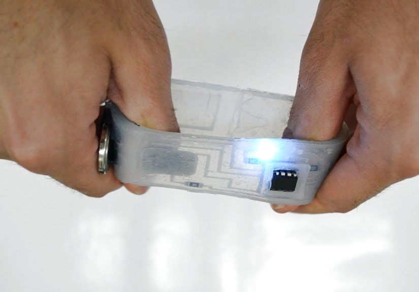
1) A stretch-reactive LED wristband
Use a stretch sensor strip as input and serpentine-wire silicone-embedded interconnects for LEDs. Stretch to brighten. Relax to dim. Instant wearable mood ringminus the astrology.
2) Soft robot joint sensor
Embed a conductive elastomer strip along a bending joint. Map resistance change to joint angle. Now your squishy robot can know where its elbow is, which is more than some humans can say after leg day.
3) Conformal pressure pad
Make a silicone pressure sensor using soft electrodes and a compressible dielectric layer. Great for props, interactive cushions, or input surfaces that don’t mind being sat on.
Conclusion: Stretchable Circuits Are a Design Mindset, Not a Single Material
DIY stretchable electronics aren’t about finding one magical “stretchy copper.” They’re about designing systems that respect mechanics: letting geometry absorb strain, isolating rigid components, choosing the right conductor strategy, and sealing everything so the real world doesn’t ruin your day.
Start simple with serpentine wire in silicone. Add sensing with conductive elastomers. Graduate to liquid metal channels when you’re ready for maximum stretch and maximum need for careful sealing. And remember: the most valuable tool in this field is not a laser cutterit’s the willingness to prototype, test, and iterate before you encase your mistakes in rubber forever.
Workshop Experiences & Maker Lessons (About )
Ask ten makers about DIY stretchable circuits and you’ll get eleven opinionsbecause one person will interrupt to argue about curing times. Still, the same “experience lessons” show up again and again, and they’re worth knowing before you start pouring silicone like it’s pancake batter.
Lesson #1: Silicone is honest. It reveals every design shortcut. If you routed a trace straight across a stretch zone, the first good pull will politely expose your optimism. Makers learn quickly to put slack into interconnectsserpentine wire paths, curved traces, gentle meandersbecause straight lines are basically a written invitation for failure.
Lesson #2: The interface is the enemy. In stretchable builds, the conductor itself often survives, but the connection point doesn’t. People report that the most common “mystery failure” is the transition between a soft conductor (wire in silicone, conductive rubber, liquid metal channel) and a hard connector (alligator clip, header pin, tiny pad). The workaround is almost always the same: build a reinforced termination zone. Make the pads bigger than you think you need, stiffen the area slightly, and add strain relief so tugging on the cable doesn’t translate into stress at the pad.
Lesson #3: Test before you seal. Silicone is a wonderful encapsulant and a terrible time machine. Once you bury a fault under two layers, you can’t go back and “just touch it up with a soldering iron.” Makers who follow layered silicone-device workflows often do quick continuity tests at every stagepads, traces, viasbecause a five-minute test beats a one-hour remake. This is especially true for multilayer approaches where a single misalignment can become a permanent feature.
Lesson #4: Bubbles aren’t just uglythey’re weak spots. People often start by mixing fast and pouring fast, then wonder why their circuit fails right where a bubble sits on top of a trace. Experienced builders mix more slowly, pour from one side, and use thin layers when they can. If someone has access to a vacuum chamber, they’ll brag about it (and honestly, they’ve earned it), but even without one, careful mixing and pouring helps a lot.
Lesson #5: Sensors have personalities. Conductive elastomers and stretch cords are fantastic for prototyping, but they can drift. Makers typically handle this with software: baseline calibration at startup, smoothing filters, and mapping functions that tolerate variation. Over time, many builders stop chasing “perfectly stable resistance” and instead design interactions that feel good even with some wigglebecause in soft systems, a little wiggle is kind of the point.
Lesson #6: Durability is a design choice. The circuits that last tend to be the ones protected from abrasion, sharp bending at one point, and connector tugging. Builders who want long-term wearables often add a top encapsulation layer, keep sensitive traces away from edges, and route channels or wires where they won’t be punctured by snaps, seams, or hardware. In other words, they treat the circuit like a wearable object firstand an electrical schematic second.
The shared takeaway from real-world DIY attempts is reassuring: you don’t need exotic tools to get stretchable circuits working. But you do need to respect the mechanics, plan your interfaces, and prototype like you’re going to be the one debugging it laterbecause you are.